Green Life Business Models · Egypt
Water Treatment Projects and Previous Work
Six interactive engineering models show the configuration of water treatment and desalination plants as they operate on the ground: independent equipment, moving flow lines, operating data, measuring points, and maintenance spaces. Select a plant, move the scene, and tap any piece of equipment to read its function and specifications.
06Various plants
3DInteractive engineering examination
360°Complete control of the scene
6 water treatment plants inside a precise engineering model
Select a plant and inspect equipment, fluid networks, power, signals, waste and alarms within a single view.
Food and beverage factories
Industrial RO plant
Operational model
The 3D plant is being prepared
GL-RO-200Industrial network water
≈FluidsϟCapacity⌁signal!Deviation
↻Rotation⌕Rounding◎Check
PROCESS SIMULATION / LIVE MASS BALANCEStable operationT+ 00:00 · Data linked to the operating status
FlowPressureQuality
SIMULATED EVENTOperational disturbance under test
The simulation displays the response of the protections and readings without changing the design specification.
Illustrative engineering model; Final dimensions and specifications are based on water analysis, site data and approved drawings.
Models of water treatment and desalination plants for different Egyptian sectors
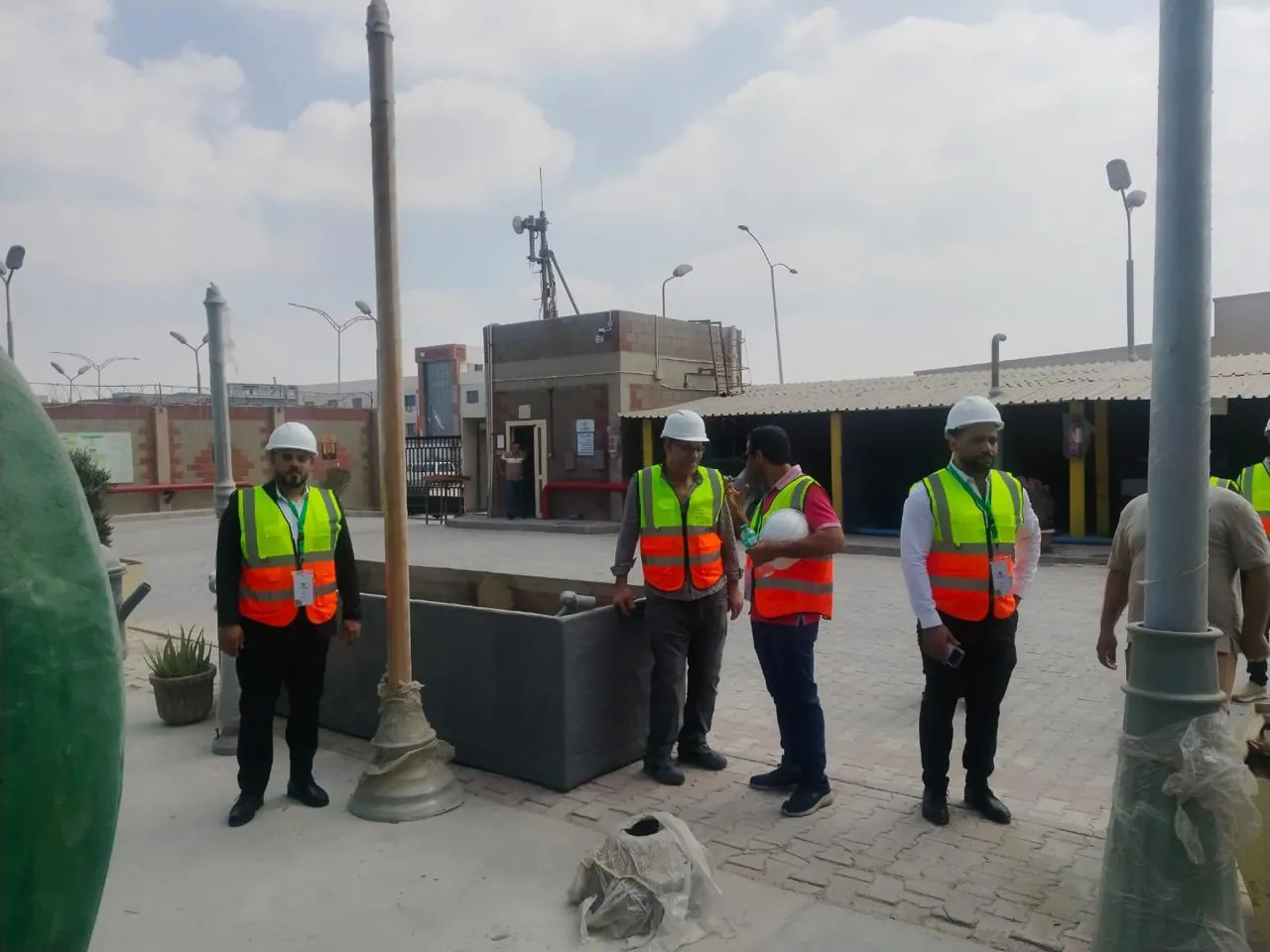
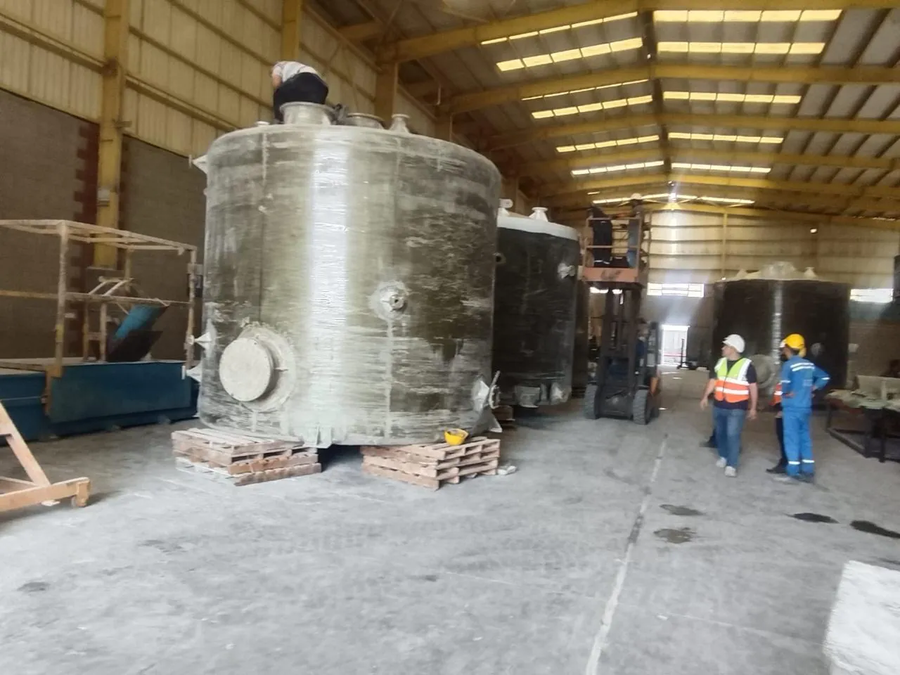
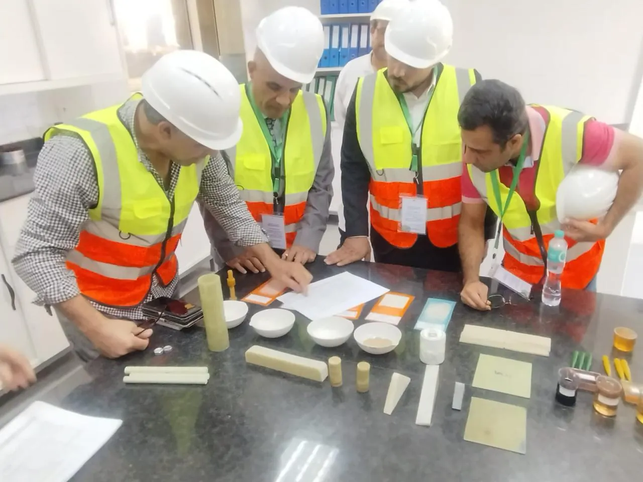
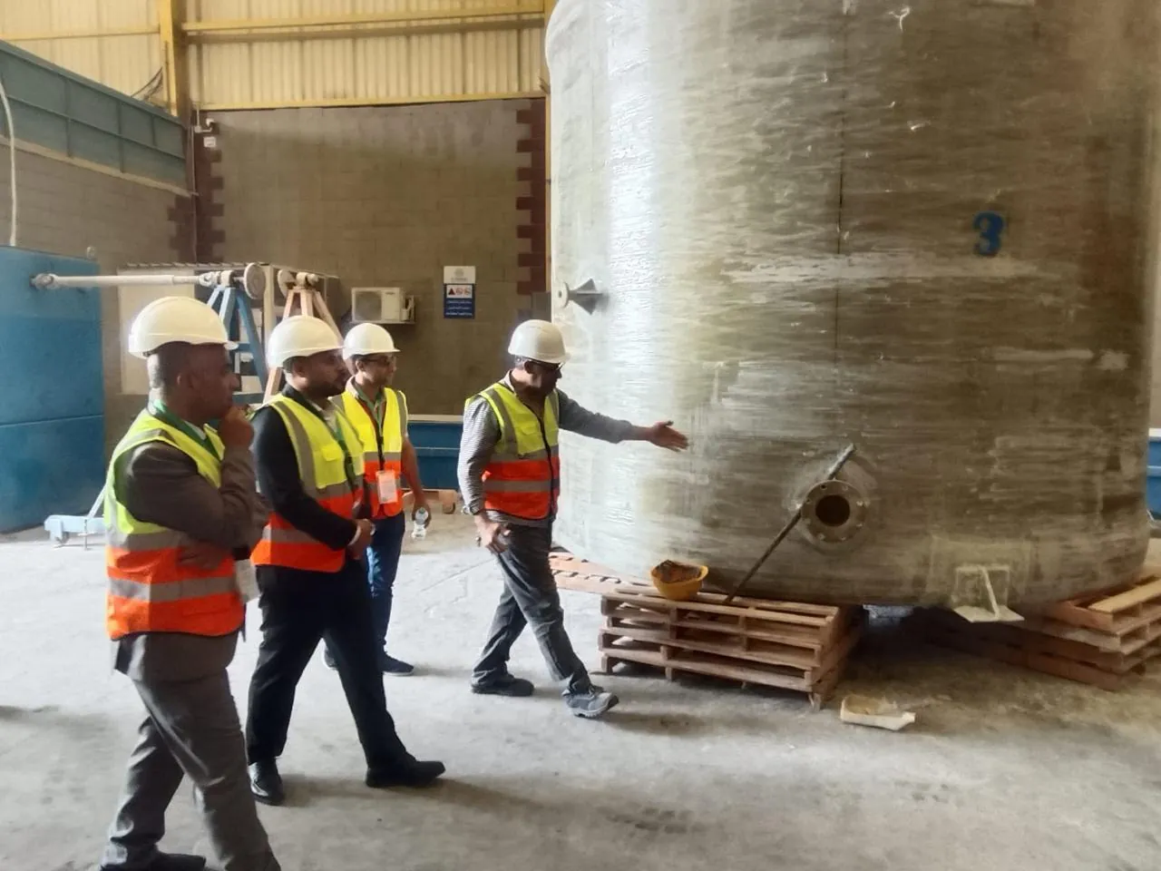
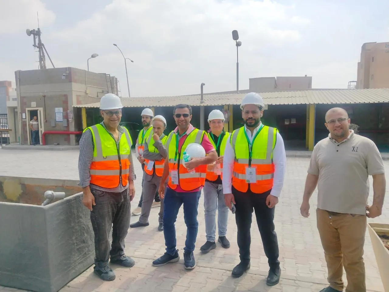
Each model below has a specific quality objective, operating risk, equipment configuration, and scope of delivery. Images of the company's work, teams, and equipment link the digital twin to field experience.
 01
01GREEN LIFE / FIELD FILEFood and beverage factories
Food and beverage factories
Industrial RO plant for a food factory with a capacity of 200 cubic meters per day
An engineering model of a food factory water treatment plant starting from a balancing tank and ending with a closed sanitary product tank. The equipment was distributed within the model according to service direction and membrane intake areas, and not as formal models; Therefore the feed line, dosing units, pressurized filters, high pressure pump, membrane vessels, reflux line, sterilizer and product tank can be checked independently.
- Source: Water network and factory tank
- Product: Low-salt process water
- Design recovery: 70–75%
- Control: PLC with conductivity monitoring
The processing line relies on a multimedia filter to reduce turbidity, a carbon filter to trap chlorine and organic compounds, and then a double softener when needed to reduce hardness before the cartridge filter. The model shows the pressure measuring points before and after each stage, the flow meter on the feed, product and return lines, and the conductivity sensor associated with the product diverter valve. When the conductivity is high, the water does not move to the production line, but rather returns to the balancing tank until the quality stabilizes. The CIP network is designed with separate connections to enable cleaning of the diaphragms without dismantling them, and the location of the manual lever and the path for changing the plugs and diaphragms have also been taken into account. This type of industrial RO plant serves mixing, final washing and boiler supply water according to the analysis and required quality limits. The final specification does not depend on capacity alone; Rather, it includes TDS, hardness, silica, iron, SDI, temperature, and operating hours pattern. The digital twin shows the impact of these inputs on pressure, recovery rate and product quality, and gives the factory team a clear visualization of the scope of supply before the blueprint is approved.
Proposed project scope
The scope of the proposed implementation includes metal bases, low- and high-pressure piping networks, power and control panels, instrumentation, commissioning, training of plant operators, delivery of maintenance schedules and critical spare parts.
 02
02GREEN LIFE / FIELD FILEFarms and greenhouses
Farms and greenhouses
Well water desalination plant for a farm and greenhouses with a capacity of 500 cubic meters per day
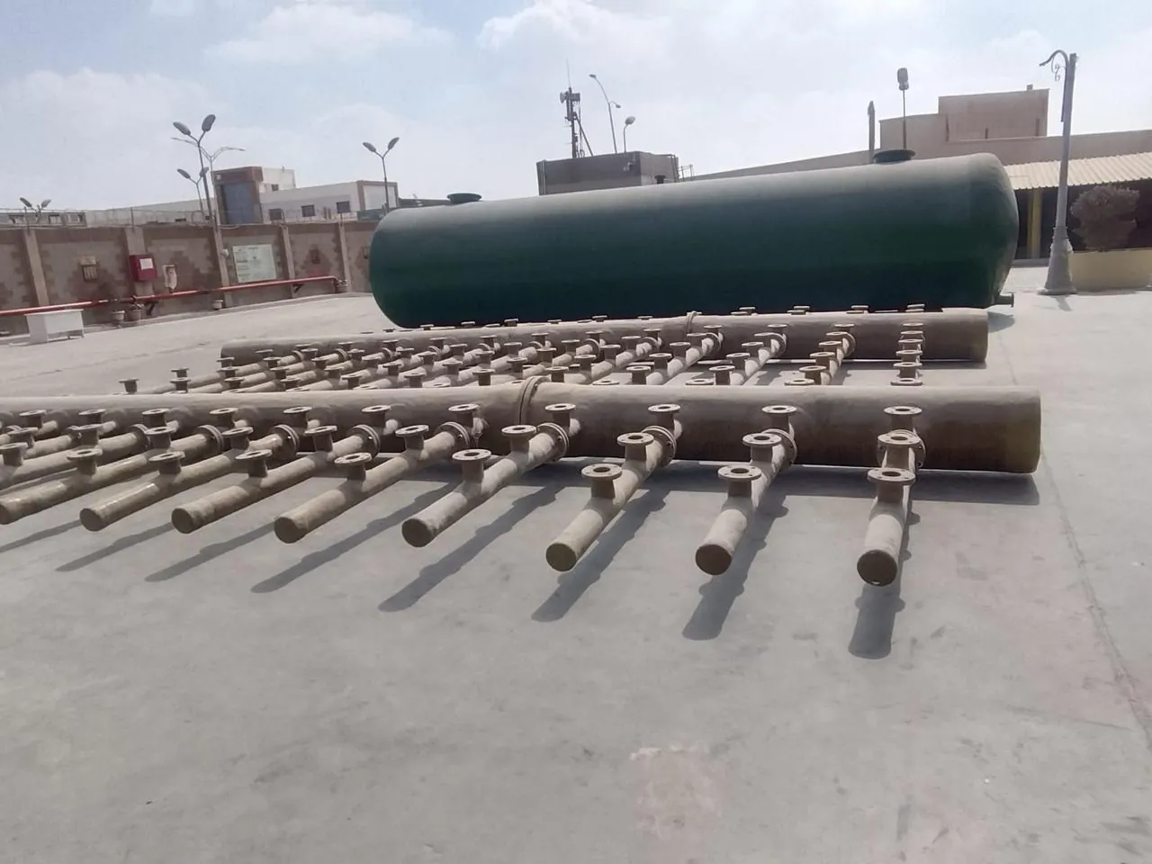
This model represents a well water desalination plant for farms, starting from the well head and air line and ending with the irrigation water tank. The path is designed to treat iron, manganese and turbidity before the water reaches the RO membranes, with clear separation between the chemical zone and the membrane zone and a safe path for backwash and reflux discharge.
- Source: High iron and salinity well
- Use: Irrigating and feeding the fertilization tank
- Treatment: oxidation, filtration, then RO
- Monitoring: pH, EC, flow and pressure
The well water is transferred to an aeration tower or an oxidation tank according to the concentration of iron and its chemical form, then it passes through filters to remove iron and manganese using media selected according to the analysis. The model shows the backwash valves, air line, sampling points, and isolation valves that allow one vessel to be maintained while the alternate line continues. After initial treatment, the water moves to the microfilter, high-pressure pump and membrane vessels designed according to salinity, temperature and silica content. The payback percentage is not set at a fixed value; The model displays its impact on sedimentation probabilities, reflux volume, and specific energy. Added an anti-sediment injection unit, a low pressure sensor to protect the pump, and a conductivity sensor on the product with automatic switching when it exceeds the limits. The product section shows a covered tank, an optional mixing unit that returns a measured portion of raw water if crop sensitivity allows, then a pumping set to the irrigation network and fertilization tank. With this structure, the farm owner can compare the cost of produced water with the required irrigation quality, and determine whether continuous or shift operation is more appropriate. The model also shows the location of the power meter and VFD panel because pump pressure control is an influential element in electricity consumption and membrane life.
Proposed project scope
The solution includes surveying the well site, reviewing the analysis, choosing a reflux disposal line, protecting the pumps from drying out, a washing program and seasonal operation, and linking the plant to the actual irrigation need instead of purchasing unused capacity.
 03
03GREEN LIFE / FIELD FILEIndustrial wastewater and reuse
Industrial wastewater and reuse
Chemical and biological industrial wastewater treatment plant with a capacity of 300 cubic meters per day
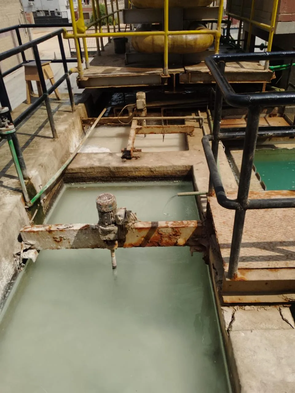
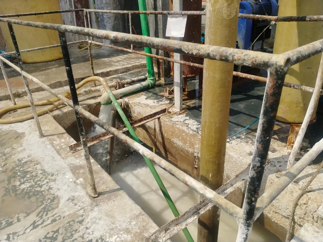
The third model is not a copy of the desalination plant; It is a complete operation diagram of an industrial wastewater treatment plant. The open and covered basins, gravity and lift lines, acidity and coagulation dosing, dissolved air flotation unit, aeration basin, final settling, sludge treatment and final filtration appear as an interconnected, inspectable system.
- Source: Production and washing lines exchange
- Stages: Balancing, DAF and Biological
- Objective: Safe reuse or conformal exchange
- Sludge: thickening and dewatering
The various flows enter the balancing basin after screening large materials, and the mixers work to prevent sedimentation and standardize the organic load before pumping. The digital twin alternately displays the aquarium level and operation of the pumps, and then the pH measuring point that controls acid or alkali dosing within the reaction tank. The water then moves to coagulation and flocculation and then DAF to separate oils and light suspended matter, with a separate line for sludge scraping and conveying. In the biological path, a network of air distributors and microcrystals appears, two blowers with an operating and backup system, and a dissolved oxygen sensor that adjusts the speed of the blowers according to the load instead of constant operation. This is followed by a final clarifier with a sludge return line and excess sludge line, then a sand filter and sterilizer when reuse is required. Added sludge dewatering plant, chemical storage area, safety barriers and operator tracks. These details prevent a misleading display based only on capacity; The choice of process is influenced by the values of COD, BOD, oils, solids, fluctuation of discharge, and toxic substances of biological activity. The model provides control points that determine plant stability, and illustrates the scenario of bypassing a DAF or isolating a basin for maintenance. It also links outlet quality to air and chemical consumption and sludge volume, which are the elements that determine the actual operating cost.
Proposed project scope
Project scope includes weighing of ponds and equipment, hydraulic calculations, processability tests as needed, odor system, control panels, bacteria start-up plan, and performance verification prior to final delivery.
 04
04GREEN LIFE / FIELD FILEMedicines and cosmetics
Medicines and cosmetics
Purified water plant for pharmaceutical factory with dual RO and UV system
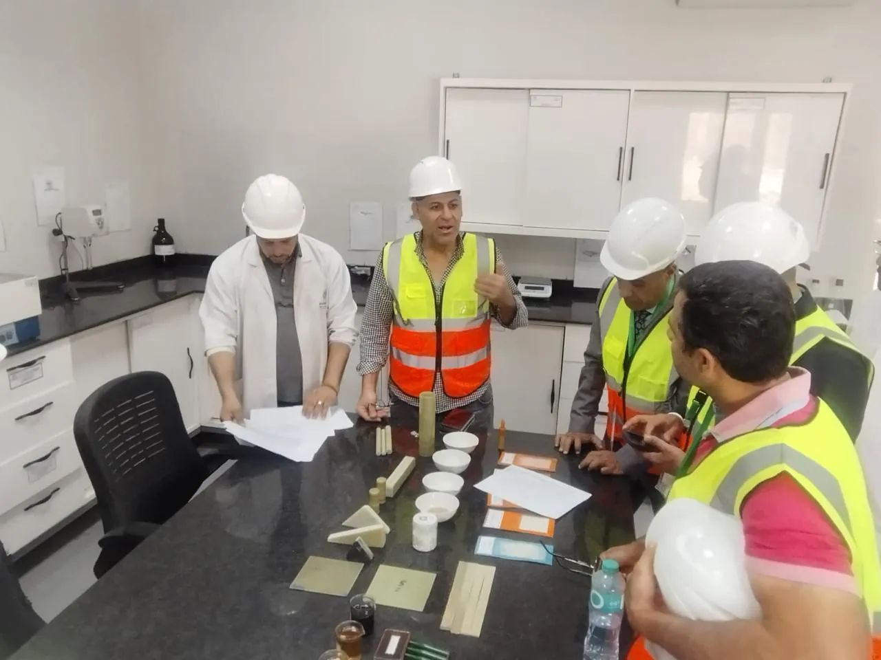
The fourth model shows a purified water plant for the pharmaceutical and cosmetics sector at a level of detail focused on preventing stagnation and cross-contamination. The plant starts with dual pretreatment, then two-stage RO, UV sterilization, a sanitary product tank and a continuous distribution loop to points of use.
- Product: Purified Process Water
- Configuration: Softener + Double Pass RO
- Disinfection: UV and hot cycle optional
- Network: Sanitary distribution loop
The plant demonstrates the separation of service water lines from product lines, the use of pipes and accessories suitable for the required quality, the slope of the distribution network and sampling points that can be sterilized. The dual softener operates with an operating and backup system to prevent production interruption during regeneration, while hardness or conductivity sensors monitor the performance of the primary treatment. After the cartridge filter, water enters the first stage of RO, and then the pH is adjusted as needed before the second stage to increase rejection and lower conductivity. The viewer shows product, return and recycling directions, the location of the CIP unit, its tank, heater and connections, and the UV unit with operating hour counter and radiation intensity. The product tank is designed with a hygienic inner surface and vent filter, and is connected to a continuous distribution loop that maintains sufficient velocity and returns water to the tank. The measuring screen displays conductivity, temperature, flow and pressure values, and indicates the positions of alarms and automatic valves. The goal of this breakdown is to define the scope of a pharmaceutical plant water project before pricing: the level of finish, piping material, weld quality, and testing and documentation protocol affect the cost as much as the processing equipment. Therefore, the business model provides a debatable picture between engineering, quality and production, and allows the definition of the points of use and their number, the loop route and the maintenance space before the final plans are issued.
Proposed project scope
The proposed delivery includes P&ID and Layout diagrams, material certifications upon request, pressure and leakage tests, instrument calibration, operation and disinfection protocol, team training, and a clear documentation package for technical review.
 05
05GREEN LIFE / FIELD FILECompounds and hotels
Compounds and hotels
Greywater treatment and reuse plant using MBR technology
This model represents a compact plant for compounds and hotels that collects gray water in an independent network and treats it for reuse in irrigation or permitted service applications. The scene is designed around the actual operating rooms: strainers, equalizers, biological treatment, MBR membranes, air blower, sterilizer and process water tank.
- Source: Showers, tubs, and sinks
- Technology: Balancing, Biological and MBR
- Use: irrigation and green spaces
- Control: levels, DO and membrane wash
The water reaches a fine, liftable and cleanable strainer and then to a balancing basin equipped with a mixer and a level sensor. This stage prevents surge loads and provides regular feeding of the biological treatment basin. Inside the MBR model are shown the membrane units submerged in the sump, the air lines used to provide oxygen and clean the surface of the membranes, and the suction pump operating based on membrane pressure. The TMP reading on the data panel changes as material accumulates, and a chemical wash alert appears when the specified operating trend is exceeded, rather than based solely on an instantaneous number. The line includes a final sterilization unit, a reuse tank and distribution pumps, with complete separation from the drinking water network and clear identification points. It also shows overflow and emergency connections, sludge drain line, ventilation areas and safe access for maintenance. This plant is suitable when site space is limited and the project requires stable quality, but its design depends on population, occupancy pattern, detergent quantity, temperature and Peak demand hours. The model displays the relationship between budget volume, residence time, membrane area, blower capacity and flow rate, so that the purchasing decision does not turn into a price comparison between unequal equipment. The operating interface helps the facility manager understand energy consumption, washing frequency, and chemical inventory.
Proposed project scope
Green Life's scope includes review of inlet and outlet networks, identification of emergency tank, design of odors and aeration, automation and alerts, biological operation, training of the facility team, and establishment of a reused water quality record.
 06
06GREEN LIFE / FIELD FILEBoilers and cooling towers
Boilers and cooling towers
Boiler water treatment plant and cooling towers for factories
The sixth model combines two service lines within one plant: boiler feed water and cooling tower compensation water. The digital twin shows common equipment and separate stages, linking water quality to the dosing program and blasting control rather than viewing the RO plant in isolation from the thermal system it serves.
- Service: Boiler Feed & Cooling Makeup
- Treatment: Softener, RO and doses
- Protection: deposition, corrosion and biogrowth
- Monitoring: Conductivity, pH and ORP
The water enters the filters and double softener and then goes, depending on the quality of the source and the boiler pressure, to the RO and the treated water tank. The model shows the salt regeneration circuit, solution tank, service and wash valves, with post-unit hardness measurement for membrane and boiler protection. The boiler line includes a degassing unit, a feed tank, and dosing pumps for oxygen binding and alkalinity control, in addition to a conductivity measurement point that controls blowing. As for the cooling tower line, it displays the tower sump, the circulation pump, and the doses of sediment inhibitor, corrosion inhibitor, and biocide, along with the ORP sensor, compensation water meter, and blowing valve. The viewer allows each circuit to be isolated and to monitor the trend of water and energy, and shows that increasing the concentration cycles reduces water consumption but requires reviewing the limits of deposition and corrosion. It also shows the location of the proposed side-current filters to reduce suspended matter and protect the exchangers. The specification for this project depends on boiler pressure, steam production rate, return temperatures, tower heat load, type of exchangers, and make-up water quality. The model provides an accurate basis for determining softener size, RO capacity, replenishment rate, chemical tank size, and the extent of automation required. The result is a technical scope that can be priced and reviewed, rather than a discrete equipment list that leaves operational risks to the plant after installation.
Proposed project scope
The solution includes water trend analysis, consumption and flushing calculation, sampling points, dosing program, safe chemical containment equipment, connection to the plant panel, and a periodic monitoring plan for water quality and heat exchange efficiency.
From workshop to operation
Implementing water treatment plants within a clear technical scope
Plant quality begins before manufacturing. The engineering team reviews water analysis, flow rates, and product limits, then produces a process diagram and list of equipment, instrumentation, and maintenance spaces. After the scope is approved, manufacturing, assembly and workshop tests begin, followed by installation, connection to the site and trial commissioning.
The interactive models on this page are used to bring technical decisions closer to the project owner: placement of each piece of equipment, flow direction, isolation and measuring points, washing needs, and access to consumable components. When an actual project begins, this vision is transformed into engineering documents linked to analysis results and site measurements.
Received a technical scope for your plant ↗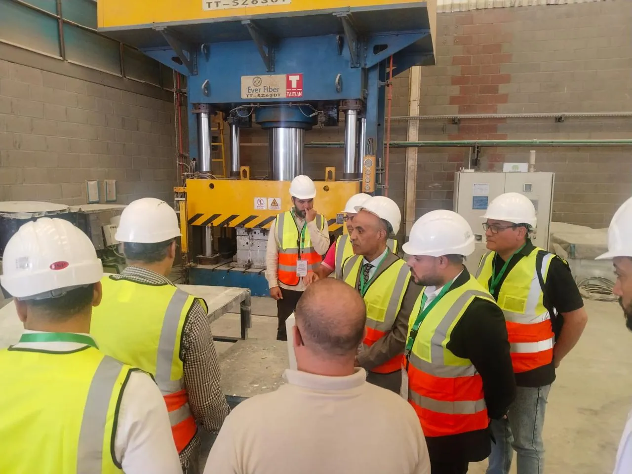
PROJECT INTAKE / EGYPT
A plant tailored to your site water and production goal
Submit water analysis, daily capacity, hours of operation, end use, and project location. The team reviews the data and determines the stages, equipment, measurement points, and initial supply scope.